News
03.09.2026FAQ: Milling

A wide range of wear patterns and damage can occur during milling, from flank wear and crater wear to built-up edges, chipping, tool breakage or vibrations. In our FAQ and troubleshooting guide, we explain the most common causes and provide practical recommendations for optimizing cutting parameters, tool geometry, coolant and machining strategies.
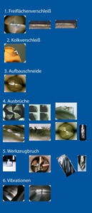
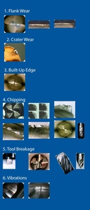
1. Flank Wear
Possible causes
- Excessive temperatures or insufficient heat resistance:
- Cutting speed
- Feed
- Coolant
- Substrate
- Coating
- Rake angle
- Protective chamfer
Corrective action – parameters
- Reduce Vc
- Increase feed per tooth to transfer more heat into the chip
- Use coolant
Corrective action – geometry
- Use a harder substrate
- Increase the clearance angle
- Reduce the protective chamfer width
2. Crater Wear
Possible causes
- Excessive temperatures or forces:
- Cutting speed
- Feed
- Coolant
- Substrate
- Geometry
Corrective action – parameters
- Reduce Vc, Vf and ap
- Use coolant
Corrective action – geometry
- Use a harder substrate
- Increase the rake angle
- Reduce the protective chamfer width
- Change the coating
3. Built-Up Edge
Possible causes
- Unfavorable machining temperatures can cause chips to adhere to the rake face:
- Cutting speed
- Feed
- Coolant
- Substrate
- Geometry
- Coating
Corrective action – parameters
- Increase Vc and Vf
- Use coolant
- Use water-free coolant
Corrective action – geometry
- Improve coating adhesion
- Increase the rake angle
- Reduce the protective chamfer width
- Change the coating
4. Chipping
Possible causes
- Combination of several factors:
- Cutting speed
- Feed
- Coolant
- Substrate
- Coating
- Geometry
- Machining method
- Tool setup
Corrective action – parameters
- Adjust Vc
- Reduce feed F at entry
- Reduce ap
- Check tool measurement and reduce overhang
- Change cooling method
- Use air / MQL
- Change machining method
- Climb milling / conventional milling
Corrective action – geometry
- Use a different substrate
- Reduce the clearance angle and/or rake angle (in combination with reducing ae)
- Increase the protective chamfer width and/or use cutting-edge rounding
- Change the coating
5. Tool Breakage
Possible causes
- Combination of several factors:
- Feed
- Substrate
- Geometry
- Machining method
- Tool setup
Corrective action – parameters
- Reduce feed F
- Reduce ap
- Use a roughing end mill
- Reduce tool overhang
- Reduce Vf and use a shrink-fit holder
Corrective action – geometry
- Use a different substrate
- Increase the protective chamfer width and/or use cutting-edge rounding
6. Vibrations
Possible causes
- Incorrect cutting parameters or insufficient stability:
- Cutting speed
- Feed
- Geometry
- Machining method
- Tool setup
Corrective action – parameters
- Reduce Vc
- Increase chip volume
- Pay attention to machining noise
- Maintain Vc and adjust f and ap to determine the settings that produce the most stable machining sound
- Check the tool setup
- Check and reduce tool overhang
- Check tool and workpiece clamping
- Reduce ap
- Change the machining strategy
Corrective action – geometry
- Use fewer teeth
- Reduce the rake angle