News
27.07.2026FAQ: Threading

Identify and solve threading issues quickly! From edge chipping and cold welding to deformed pressure flanks, a wide range of wear patterns can occur during threading. In our FAQ & Troubleshooting Guide, we explain the most common causes and provide practical recommendations for optimizing cutting parameters, tool geometry, coolant, and the machining process.
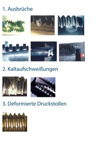
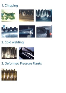
1. Chipping
Chip Jamming During Reverse Rotation
Occurs when chips are not evacuated properly.
Possible Causes
- Cutting speed
- Geometry
- Chip evacuation problems
Corrective Measures via Parameters
- Optimize cutting parameters
Corrective Measures via Geometry
- Adjust helix angle
- Improve chip evacuation
Individual Tooth Chipping
Occurs when chips are not evacuated properly.
Possible Causes
- Cutting speed
- Geometry
- Coating
- Chip evacuation problems
Corrective Measures via Parameters
- Increase or decrease cutting speed (Vc)
Corrective Measures via Geometry
- Reduce relief grind
- Change or add coating
- Use a different tap
Chipping on the Rake Face
Occurs during reversal of rotation or when the material causes the tool to bind.
Possible Causes
- Cutting speed
- Geometry
- Coating
- Chip evacuation problems
Corrective Measures via Parameters
- Increase coolant concentration
- Use a larger drill diameter
Corrective Measures via Geometry
- Apply greater relief grind
- Increase wear resistance:
- Coating
- Substrate
Wear-Related Chipping
A specific type of chipping caused by work hardening.
Occurs during reversal of rotation or when the material causes the tool to bind.
Possible Causes
- Cutting speed
- Coolant
- Geometry
- Substrate
- Coating
- Chip evacuation problems
Corrective Measures via Parameters
- Increase coolant concentration
- Improve drilling operation (TRS)
Corrective Measures via Geometry
- Greater relief grind
- Shorter chamfer length (cutting edges engage more effectively)
- Increase wear resistance:
- Coating
- Substrate
Chipping on the Tool Face
Occurs due to collision with the bottom of the hole.
Possible Causes
- Machining method
- Setup
Corrective Measures via Parameters
- Avoid contact with the hole bottom
- Check travel distance
- Check position
- Check tool length
- Check hole depth
Corrective Measures via Geometry
- Greater relief grind
- Shorter chamfer length (cutting edges engage more effectively)
- Increase wear resistance:
- Coating
- Substrate
Chipping on the Chamfer
Possible Causes
- Geometry
- Substrate
- Coating
- Machining method
- Setup
- Tap drill hole
Corrective Measures via Parameters
- Use a larger tap drill size
- Check position (program)
- Check runout
Corrective Measures via Geometry
- Use a tougher substrate
- Increase rake angle
2. Cold welding
Possible Causes
- Cutting speed
- Geometry
- Coolant
- Coating
Corrective Measures via Parameters
- Reduce cutting speed
- Use a different coolant or increase coolant volume/concentration
Corrective Measures via Geometry
- Modify relief grind
- Add or change coating
3. Deformed Pressure Flanks
Occurs when the material undergoes plastic deformation and the tool becomes jammed.
Possible Causes
- Cutting speed
- Geometry
- Coolant
- Coating
Corrective Measures via Parameters
- Reduce cutting speed
- Use a different coolant or increase coolant volume/concentration
- Increase drill diameter
- Improve drilling operation (TRS)
4. Checklist
- Are the cutting speed and feed rate correct?
- Is the coolant suitable?
- Is the coolant volume, positioning, and concentration correct?
- Is the tool position correct?
- Is the tap drill diameter correct?
- Has the material work-hardened?
- Is the thread tool geometry suitable?