News
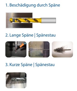
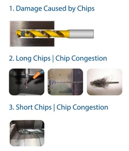
08.05.2026FAQ: Drilling Part 3 | Chips

Whether short, controlled chips or long, ribbon-like chip bundles – chip formation provides important insights into the condition of the machining process. In this FAQ, we explain which chip forms are critical during drilling, what causes them, and which corrective measures help stabilize chip evacuation reliably.
1. Damage Caused by Chips
Possible Causes
- Often caused by poor interaction between:
- Cutting speed
- Feed rate
- Geometry
- Setup
- Machining strategy
- Coolant
Corrective Measures via Parameters
- Reduce cutting speed
- Reduce feed rate
- Consider cross holes or interrupted cuts
- Use coolant with a higher oil content
- Check tool setup
- Check runout
- Ensure secure workpiece and tool clamping
Corrective Measures via Geometry
- Increase point angle
- Use larger chip flutes
- Reduce helix angle
- Consider or prefer horizontal machining
- Increase taper
2. Long Chips | Chip Congestion
Possible Causes
- Mainly occurs in ductile materials due to:
- Cutting speed
- Feed rate
- Coolant
- Coating
- Machining strategy
- Chip evacuation
- Geometry
Corrective Measures via Parameters
- Reduce cutting speed
- Increase feed rate
- Increase coolant flow rate
- Introduce pecking cycles
- Consider chip evacuation issues
- Check and adjust the Vc/Vf ratio
Corrective Measures via Geometry
- Optimize coating
- Reduce margin width
3. Short Chips | Chip Congestion
Possible Causes
- Often caused by poor interaction between:
- Cutting speed
- Feed rate
- Geometry
- Chip evacuation
- Machining strategy
- Coolant
- Coating
Corrective Measures via Parameters
- Reduce cutting speed
- Increase feed rate
- Increase coolant flow rate
- Increase coolant pressure
- Introduce pecking cycles
- Address chip evacuation problems
- Check Vc/Vf ratio
Corrective Measures via Geometry
- Optimize coating
- Reduce margin width
- Reduce core diameter
- Increase helix angle
- Polish flutes
- Adjust flute length
![]()