News
26.02.2026FAQ Drilling Part 1 | Wear

Whether it’s unexpectedly short tool life, increasing cutting forces, or poor surface finish: wear in drilling operations usually becomes apparent at an early stage – if the typical signs are interpreted correctly.
This FAQ outlines the most common wear patterns, explains their causes, and provides proven corrective measures to systematically improve tool life.
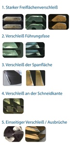
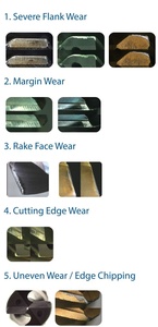
1. Severe Flank Wear
Severe flank wear primarily occurs where the tool flank face remains in continuous contact with the workpiece. This wear leads to increasing cutting forces, reduced dimensional accuracy, and ultimately shorter tool life.
Possible Causes
Flank wear is often classified as “normal” – however, the following factors can accelerate it:
- Excessive cutting speed
- Unsuitable feed rate
- Insufficient coolant supply
- Inappropriate substrate
- Unsuitable or missing coating
- Incorrect setup
- Inappropriate tool geometry
Corrective Measures – Parameters
- Reduce cutting speed (Vc)
- Increase feed rate
- Ensure consistent coolant application and increase oil concentration
- Ensure sufficient cutting edge stability
Corrective Measures – Geometry
- Select a more wear-resistant substrate
- Adapt or add coating
- Increase primary clearance angle
2. Margin Wear
Wear on the margin is caused by continuous friction between the margin and the bore wall. It negatively affects dimensional accuracy and surface quality of the hole.
Possible Causes
This wear can be considered “normal,” but is mainly promoted by:
- Excessive cutting speed
- Insufficient coolant supply
- Incorrect setup
- Inappropriate tool geometry
Corrective Measures – Parameters
- Reduce cutting speed (Vc)
- Optimize coolant supply; adjust oil concentration and flow rate
- Feed marks often indicate dry machining – review the process
- Ensure machine and tool stability as well as proper runout
- Adjust tool life criteria
Corrective Measures – Geometry
- Increase back taper
- Reduce margin width
3. Rake Face Wear
Rake face wear is primarily caused by friction from chips sliding along the rake face during drilling. This abrasive contact results in material removal and can significantly reduce tool performance and tool life.
Possible Causes
- Abrasive wear due to strong chip friction on the rake face
- Frequently occurs in deep hole drilling with external coolant supply or internal coolant supply (through-coolant) at insufficient pressure:
- Excessive cutting speed
- Unsuitable feed rate
- Insufficient coolant supply
- Inappropriate substrate
- Unsuitable machining method
Corrective Measures – Parameters
- Reduce cutting speed (Vc)
- Reduce feed rate
- Optimize coolant supply
- Ensure machine and tool stability as well as proper runout
- Drill in multiple steps (peck drilling) to improve chip evacuation
Corrective Measures – Geometry
- Use a more wear-resistant substrate
- Apply alternative coatings
4. Cutting Edge Wear
Cutting edge wear occurs due to the direct engagement of the cutting edge with the material and the resulting high mechanical loads. It leads to reduced sharpness, increasing cutting forces, and shorter tool life.
Possible Causes
Primarily occurs in thin materials, through holes, cross holes, and interrupted cuts. Contributing factors include:
- Excessive cutting speed
- Unsuitable feed rate
- Insufficient coolant supply
- Inappropriate substrate
- Unsuitable machining method
- Inappropriate tool geometry
Corrective Measures – Parameters
- Reduce cutting speed (Vc)
- Reduce feed rate
- Reduce load at hole exit
- Increase oil concentration of the emulsion
- Ensure machine and tool stability
- Optimize runout
Corrective Measures – Geometry
- Apply a radius or chamfer to the cutting edge
- Increase back taper
- Modify margin design (width/design)
5. Uneven Wear / Edge Chipping
Uneven wear occurs when the tool is not centered or stably guided during engagement. As a result, one side of the cutting edge carries more load than the other, leading to asymmetric material removal, increased cutting forces, and dimensional deviations.
Possible Causes
- Occurs almost exclusively in horizontal machining operations:
- Setup-related issues
Corrective Measures – Parameters
- Ensure proper tool alignment
- Check stability and runout
![]()